
HARDWARE MANUAL
Overview
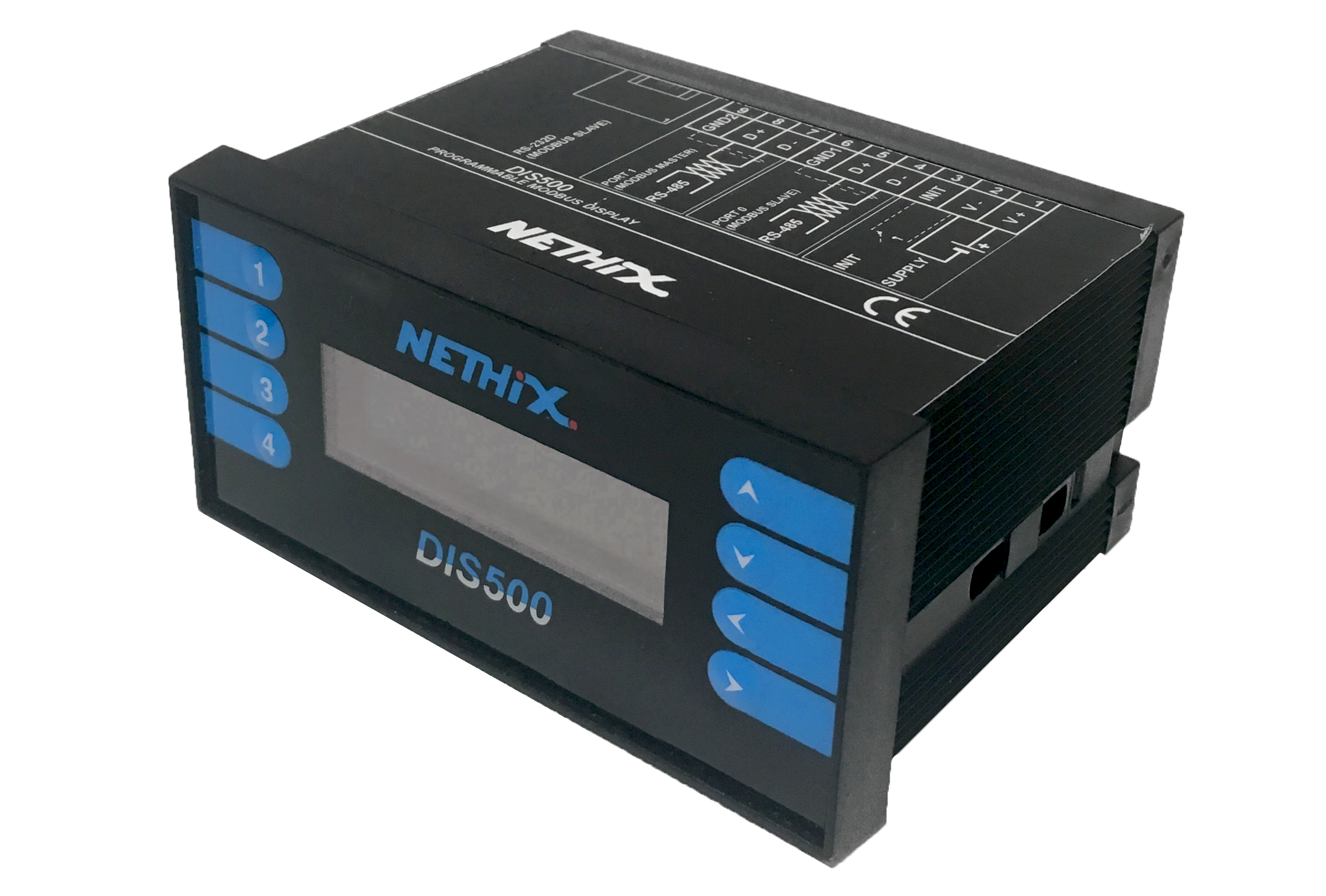
DIS500 is a programmable display for control panels, suitable to communicate through Modbus RTU protocol on serial port RS232 and RS485. It can be used as a slave device for displaying the data managed by the WE300 and WE500. Having a Master port RS485 on board it can also interrogate slave devices (as for example the expansion modules XP500) and operate as a Modbus gateway. The configuration of the functions and registers of DIS500 can be performed through the Software DIS Configurator.
DIS500 is compatible with the whole range of Nethix products, nevertheless it can be used with any other device, supporting the standard Modbus protocol.
In this section all technical specifications of the device are described.
Technical characteristics
4AI-I
The graphic display DIS500 has the following technical features:
|
Description |
Graphical display with master and slave Modbus RTU protocol
|
|
Power supply |
10 / 30 VDC
|
|
Average consumption |
45 mA @ 24 VDC
|
|
Protection reverse polarity |
60 VDC max
|
|
Insulation |
1500 VAC 50 Hz, 1 min.
|
|
Operating temperature |
-20°C / +60°C
|
|
Storage temperature |
-30°C / +80°C
|
|
Humidity |
-10°C / +60°C
|
|
Storage temperature |
-40°C / +85°C
|
|
Humidity |
0 / 90% (non condensing)
|
|
Dimensions |
96 x 48 x 74 mm
|
|
Weight |
128 gr
|
|
Enclosure |
For panel mount, black self-extinguishing plastic
|
|
Connections |
2 x RS485 on terminal, 1 x RS232D on RJ-45
|
|
Protocol |
Standard RTU Modbus
|
|
Communication speed |
Up to 38400 bps
|
|
Standard |
EN 61000-6-2, EN 61000-6-4
|
|
Display |
132x32 pixel, 13.2x48.1 mm
|
Installation
The device DIS500 can be mounted on panel using the included assembly kit. It’s recommended to install the display in a sheltered place repaired from vibrations, and to avoid the installation near power signal cables, that might generate disturbance.
Frontal view and button panel
On the front of the device, some multifunction-buttons are positioned near the display:

The buttons allow to browse through the available pages inside DIS500 and may have different functions according to the visualization type:
IN VISUALIZATION MODE:
The buttons allow to browse through the graphical pages.
Press the button UP to scroll upwards and DOWN to scroll downwards
The buttons have no effect, if a single page is loaded.
ACCESS TO THE PRESET MENU:
In order to enter the preset Menu, where it’s possible to change the value of the configured registers, keep the button RIGHT pressed and press UP.
Use the buttons UP and DOWN to select the parameter to be modified. Once found the desired parameter, press FOUR to highlight the first character of the parameter and then use the buttons UP and DOWN to scroll the available numbers/characters. Once set the required character/number on this position, press the buttons RIGHT and LEFT to skip to the following (or to the previous).
To confirm the modifications press the button FOUR; in alternative, to escape and cancel the modifications made, push the button THREE.
ENTER THE CONFIG MENU:
For entering the config Menu, it’s necessary to pass through the preset menu. From the preset menu, press the button ONE.
Once entered the config menu, it’s possible to proceed with the visualization/modification of some general parameters of the device:
- Baud485 it shows the communication speed of the RS485 slave port
- Baud232 it shows the communication speed of the RS232D slave port
- Master it shows the communication speed of the RS485 Master port
- Address it shows the Modbus address of the device
- Bright it allows to change the brightness of the display, setting a value between 1 (minimum) and 15 (maximum)
- Contrast it allows to set the display contrast. The positive values go from 1 (minimum) up to 15 (maximum), the negative from 16 (minimum) up to 31 (maximum)
- Firmware it shows the firmware version currently installed on the device
- Status it shows the operative condition of the device: RUN means that the device is working, STOP indicates that no program has been loaded in the device yet.
To select the parameter, that has to be changed, it’s required to push the buttons UP and DOWN to scroll up and down the list. Once found the required parameter, push the button FOUR to change it and use UP and DOWN to scroll through the different available options.
To confirm the modifications, just press the button FOUR, or press THREE to cancel the modifications and return to the main page.
Rear view and terminals
On the backside of the DIS500 are available all clamps for the power supply connection, for the serial ports and the RJ45 connector.

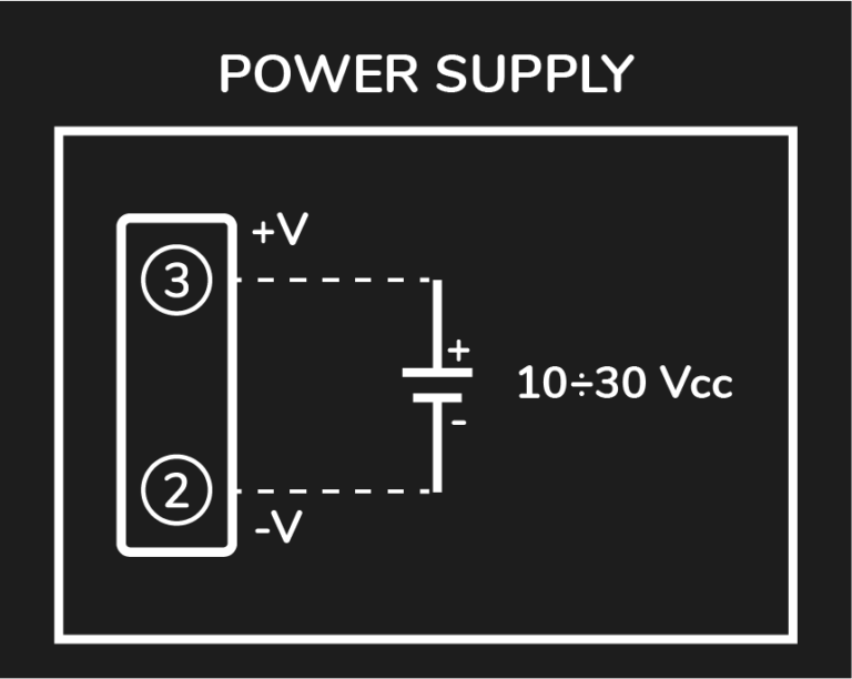
POWER SUPPLY
The power supply range supported by DIS500 is of 10/30VDC.
The power supply is led to clamps 1 and 2 as shown on the following picture:
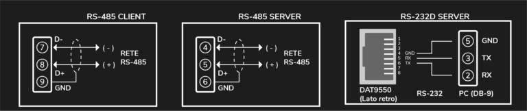
SERIAL PORTS CONNECTIONS
DIS500 has a Master RS485 Serial port, a Slave RS485 serial port and a Slave RS232D serial port:
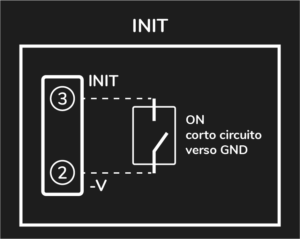
INIT mode
At any time the DIS500 can be set in INIT mode, in order to have it back to a known condition and be able to communicate with it. For restoring the INIT mode, make the connection as shown on the picture below, having the device turned off.
The communication parameters in INIT mode are:
- Baudrate 9600
- Slave address 10
Using the above mentioned parameters and the software DIS Configurator, set a speed value and a slave address. To make the modifications effective, just turn off the DIS500, remove the connection to the clamp INIT and reboot the device.
Safety guidelines
- This device is only suitable for being installed by a qualified operator
- Nethix is not responsible for improper use and/or its side effects
- Nethix products are designed for typical use in industrial automation and/or home applications. If you plan to use Nethix products in special applications where anomalies and discontinuity of service can have serious effect on human life or can cause physical or material damages, or where extremely high levels of reliability are required (for example in aerospace systems, in atomic energy control systems or n electro-medical devices), please contact Nethix for support to your particular application. Nethix is not responsible of damages caused from its products if such applications are not previously authorized.
The product shall not be treated as household waste. It shall be instead handed over to an appropriate collection point for the recycling of electrical and electronic products. For further information about recycling of this product, contact the local city office and/or the local waste disposal service.